4-20mA Question (Impedance Limits)
Question:
What problems (if any) will occur in the loop shown below?
Assume the transmitter is a Rosemount 5301 level safety transmitter with 4-20mA +HART output being used as part of a SIL2 safety instrumented function.
See answers and explanations below diagram.
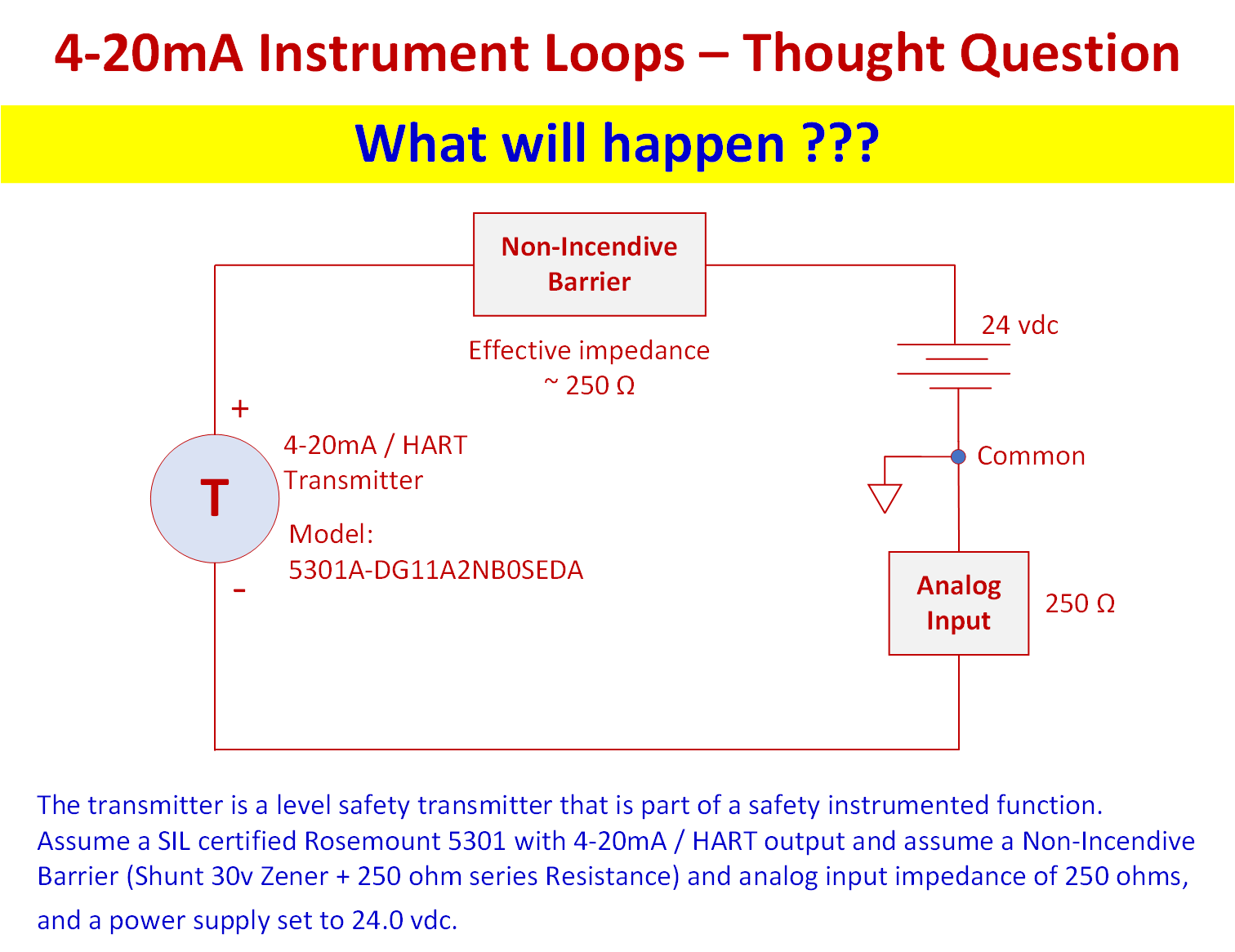
Loop Impedance Problem
Answer:
The first step in understanding this problem is to recognize the excessive loop impedance. This loop has a total of approximately 500 ohms of impedance.
The next step would be to review the reference manual on info related to this, factoring in that it is being used in a safety instrumented system (SIS).
In this case, section 6.1 of the Rosemount 5300 Series Ref Manual (00809-1600-4530, Rev AA) states the following:
The loop must be designed so that the terminal voltage does not drop below the minimum input voltage when the transmitter output is 22.5 mA. See values in Table 6-1.
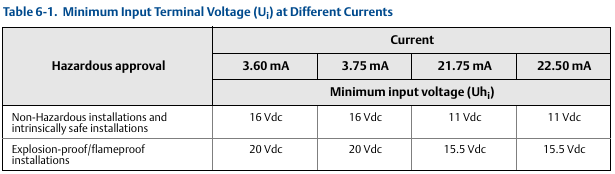
The reason for this exceptionally high minimum voltage restriction is so that the transmitter can still perform all relevant functions even at a maximum output current of 22.5 mA (high fault current). This is necessary to satisfy SIS standards (IEC 61511 / ISA 84).
Note The actual high fault current may be set as low as 21.75mA depending on your plant or system's SIS standards for fault alarm values.
Rosemount 5300 series transmitters, and many other SIL certified instruments perform a power-up sequence that includes a low fault and high fault current test to verify impedance and voltage dynamics of the loop are suitable for full output range.
What will happen?
In short, the transmitter would refuse to startup.
In this case, when the transmitter goes into the high fault current test during startup, it will detect that the transmitter terminal voltage is below the minimum acceptable limit (this is because of the excess voltage being dropped across the 500 ohms of total loop impedance), so it will revert to the low fault current value to help communicate a problem (fault) to HMI - so the humans can figure it out and fix the problem.
Here is math for the high current fault test if you are interested:
If we had 22.5 mA current, with 500 ohms of total loop impedance and 24.0v power, we would have a 11.25v total drop across the NIB and analog input combined, which would only leave 12.75v available across the transmitter terminals - and this is below the specified minimum voltage of 15.5vdc per table 6-1 of the Rosemount 5300 series Reference Manual .
So... the design is flawed. But this real situation happens all the time...Many I&C engineers are assuming that all instruments still work exactly like those from 20-30 years ago and failing to read the manuals...
What is the solution?
The only truly correct pathway would be to redesign the system, possibly replacing NIB with another form of protection/isolation, or other solutions.
Is there a trick to 'just get it running again'?
There is a 'way to get it running again' that is often used in these cases - but it is a very bad practice and should not be used.
Sometimes technicians will simply jumper out the NIB temporarily to get the transmitter to pass the high current startup test that is causing the problem. *Any time an I&C tech is using a jumper, they should be thinking "wait - what the heck am I doing".
Not only does this defeat the ignition protection provided by the NIB, it also can leave dangerous undetected failures in the system and will compromise the SIS program.
While they may get the transmitter to start up and appear to run by jumping out the NIB, when the transmitter reaches higher output current levels it may suffer various problems due to reaching the lower voltage limit of the transmitter. Some of the possible problems that may arise include:
- Reaching a flatline (saturation) point that is below expected value and possibly even below 100% or below a trip point. Level is rising, but the indication isn't...
- The HART communications could be lost as the transmitter reaches voltage limits and no longer has the margins to modulate signal voltage for communications.
- Note - when this occurs it can be challenging, because the transmitter will be stuck in whatever mode it was in when you lost comms.
- To reconnect you would need to lower the transmitter output signal so that it's below saturation - but if you were doing an output test to drive the signal and then you lose comms, you may have to restart the transmitter to get out of the high current / low voltage trap - but of course, it fails the high fault current test in startup. It becomes a nightmare - so the right answer is to redesign the system.

About the author
Mike Glass
Mike Glass is an ISA Certified Automation Professional (CAP) and a Master Certified Control System Technician (CCST III). Mike has 38 years of experience in the I&C industry performing a mix of startups, field service and troubleshooting, controls integration and programming, tuning & optimization services, and general I&C consulting, as well as providing technical training and a variety of skills-related solutions to customers across North America.
Mike can be reached directly via [email protected] or by phone at (208) 715-1590.