Solution to Brain Teaser (4-20mA Loop Faults)
BRAIN TEASER FOR INSTRUMENT TECHS:
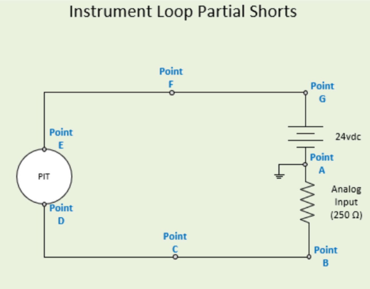
In the diagram shown, which of the following scenarios would cause the HMI value to indicate LOWER than the associated transmitter PV value???
For this problem, assume that the negative side of power supply is common/grounded.
A) Approximately 10KΩ short between transmitter housing between Points D & E (assume transmitter case is properly grounded) due to moisture buildup in the transmitter housing.
B) Approximately 10KΩ short in conduit run between Point C & ground due to a conduit run filling with water and insulation damage on the instrument cable caused by poor installation practices.
C) Approximately 10KΩ short in conduit run between point F & ground due to a conduit run filling with water and insulation damage on the instrument cable caused by poor installation practices.
CLUES:
One of the commonly overlooked (and/or misunderstood) problems in instrumentation systems is signal current leakage in 4-20mA loops. Problems along these lines are also a great way to gauge someone’s understanding (and experience level) with troubleshooting instrumentation problems.
Instrument Techs learn early in our careers that current flow is [theoretically] the same throughout the entire 4-20mA loop. However, when moisture or other potential leakage sources are introduced, the simple ‘series’ circuit gains parallel branches which can allow the current flow to be different at various parts of the current signal loop – and things get interesting.
One of the most common causes of these problems is moisture or condensation buildup within conduit runs, J-boxes, and even control panels. We will talk about how to prevent these problems in a later blog….
When conductive liquid interacts with our theoretically simple 4-20mA loop, the signal current at the field device (transmitter, positioner, etc.) could be higher or lower than the current at the controller IO cards, due to current leakage around the field device or around the IO cards, and/or between the field device signal wires and/or common or ground.
THOUGHT OBJECTIVE:
The question and diagram shown is intended to stir thought about the current loop and to help people see the value of doing a little deeper analysis during troubleshooting.
Once you understand this concept, if you keep your eyes open for it, you’ll begin to find these problems with surprising regularity (especially if you work in facilities that often end up with moisture or liquids in your conduit runs, J-boxes, and panels).
For an additional challenge, try to approximate the transmitter PV and HMI EU value under answer option B, if the transmitter was calibrated for 0-5000 psig = 4-20mA, and is currently at 2000 psig.
Solutions is below the image:
SOLUTION:
Correct Answer:
The only option listed that causes the HMI value to be LOWER than the transmitter PV is option B.
Option B - A partial short between point C and ground will allow some of the 10.4mA current from the transmitter to 'bypass' the PLC via ground path, resulting in less than the full 10.4mA flowing across the PLC’s analog input card.
To determine exact value for this scenario, you can find the equivalent resistance of 10K/250 ohm parallel of the PLC analog input (which is 243.9 ohms). Then, simply calculate the voltage across the 243.9Ω at 10.4mA, which results in 2.53656v
This is 38.414% of 1-5v signal range of AI card (based on 4-20mA x 250 ohms).
38.414% of 0-5000 scale lands at 1920.7psig (or close to that, depending how far you round in calcs).
Incorrect Answers:
Option A - A partial short across transmitter terminals, such as transmitter housing filled with water would cause the HMI value to read HIGHER than transmitter PV, because of the additional current that would flow ‘around’ the transmitter due to voltage applied across the partial path (10K assumed here).
Option C (partial short across 24v power supply) would not impact the current between the transmitter and the PLC analog input so the HMI would still MATCH the transmitter PV assuming proper calibration, etc..
Some Notes:
I especially appreciate what Brad Burton pointed out about the built in Diagnostics of many modern transmitters.
This brilliant feature effectively determines the baseline loop impedance of the loop (based on voltage at the transmitter as
it runs through the full-scale during power up). It uses this baseline curve of transmitter voltage vs current to determine if the loop dynamics such as power supply voltage or loop impedance has changed. If the loop characteristics change, a diagnostic alert can be generated and viewed on transmitter screen or communicated (via HART, etc.) to a connected monitoring & management system such as Emerson AMS, Honeywell FDM, etc..
Sadly, even in plants that have thousands of transmitters with these capabilities, they are often unutilized simply because not enough Engineers or Techs in the field understand the technology (or they fail to see the incredible value this provides).
In short: If something goes wrong with the 4-20mA loop, such as current leakage due to water ingress into conduit, j-boxes, or transmitters, or if power supply issues arise, the loop integrity diagnostics will notice the change and can provide an alert/warning to the maintenance team, often before it becomes a bigger problem, so you can fix the problem before it’s a crisis; before it’s a safety issue; or before it costs thousands or millions of dollars…
For plants and equipment with wet processes or that are exposed to high humidity or weather, the importance of instrument and electrical panel seals and glands hopefully becomes more apparent in this discussion. Too many techs seem to disregard the importance of preventing moisture buildup (even via humid air). Even if the panel only has a small opening at the bottom, moisture laden air can cause a buildup of condensation which can lead to problems similar to those noted above…
Final Thoughts:
Understanding how 4-20mA loops and Smart transmitters actually work is critical, and far too few technicians (or engineers) have an adequate understanding of these concepts. And therefore, we see a lack of implementation and utilization of these powerful features and functionality that could/should be saving industry billions of dollars.
In my travels, I have found common weaknesses by a huge portion of technicians and engineers on the details of the 4-20mA loops, as well as unawareness of the benefits, advantages, or proper implementation of modern ‘Smart’ instrumentation. Even many senior techs and engineers could use an update on this technology – and that is evident by the lack of proper implementation or utilization in so many plants and facilities.
All of the information is available in manuals, textbooks, and other locations (in pieces) – but it is often without the context of how it can actually help. Hopefully, the problem I proposed here helps a few people see and better understand some of the ways we could be preventing headaches, improving safety, and saving millions of dollars in our facilities.
This is an example of the types of things that we emphasize in our Instrumentation & controls courses. We don’t simply cover the generic textbook info that you can read whenever needed – we help people understand the important topics like this, that are causing problems and/or preventing plants and technicians/engineers from reaching full capabilities.

About the author
Mike Glass
Mike Glass is an ISA Certified Automation Professional (CAP) and a Master Certified Control System Technician (CCST III). Mike has 40 years of experience in the I&C industry performing a mix of startups, field service and troubleshooting, controls integration and programming, tuning & optimization services, and general I&C consulting, as well as providing technical training and a variety of skills-related solutions to customers across North America.
Mike can be reached directly via [email protected] or by phone at (208) 715-1590.