Data Corruption - Part 3 (Input Accuracy & Precision Problems)
More causes of bad data...
This series on Data Corruption in Control Systems explores the most common—yet frequently overlooked—problems affecting industrial control system performance and associated data & analytics.
In part 1, we discussed Signal Filtering. In part 2 we covered Digital Resolution & Degradation issues. In this part (part 3), we are covering Input Accuracy & Precision, and in part 4, we will cover Output Device Behaviors & Impacts.
Data Corruption - Part 3 (Input Accuracy & Precision Problems)
One of the biggest problems with I&C data is due to fundamental instrumentation errors in the field measuring equipment errors. In this article, we will go over seveal of the most common types of problems that cause data errors directly from the source of the measurement, including:
- Incorrect sensor setups & configurations
- Improper instrument installations
- Improper instrument selections
- Unsanctioned, incorrect, or misguided field modifications
- Poor maintenance practices
- Worker competency issues
So – lets dig in, starting with item #1 above. Note – To keep the length reasonable, I am only going to cover the most common sources of problems.
1. Incorrect Sensor Setups & Configurations
1.1 RTD Issues
Key Problems:
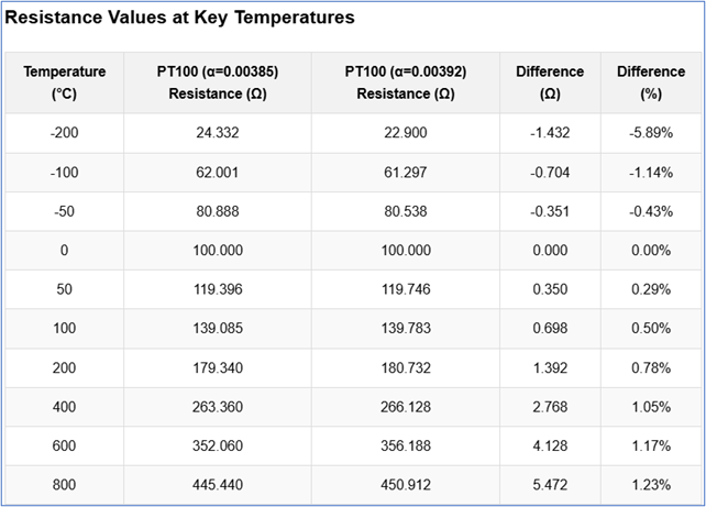
- Wrong Alpha Value Configuration: RTD Sensors are usually not marked - so it can be difficult to determine what the prior sensor was when replacing them. You need to confirm that the transmitter sensor configuration matches the sensor you are installing. Ideally this would all be spelled out on a spec sheet (or instrument data sheet). How much difference does it make? quite a bit. Check out the following: Using alpha 0.00385 when sensor is 0.00392 creates temperature-proportional errors. These errors will be more pronounced further from 0C and could be as much as 10C at 300C or 20C at 850C. See table below for examples:
- Incorrect Wiring Configuration: Mismatching 2/3/4-wire RTD with transmitter settings introduces lead resistance and/or compensation errors.
- Lead Compensation Configuration Errors: Unequal lead resistances in 3-wire configurations causing compensation errors.
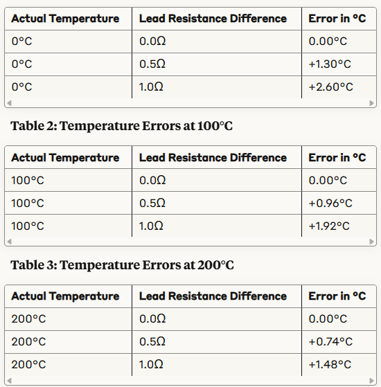
Note – 4-wire RTD configurations are much more resilient to differences in lead resistance.
- Self-Heating Effects: Measurement current creates heat that varies with installation conditions, creating inconsistent errors. Note – This is usually not a problem on higher resistance RTDs and/or higher temperature measurements.
Solutions:
Document installed sensor specifications and carefully verify transmitter configuration matches actual sensor type and wiring.
Ensure proper maintenance and installation/commissioning methods.
1.2 Thermocouple Issues
Key Problems:
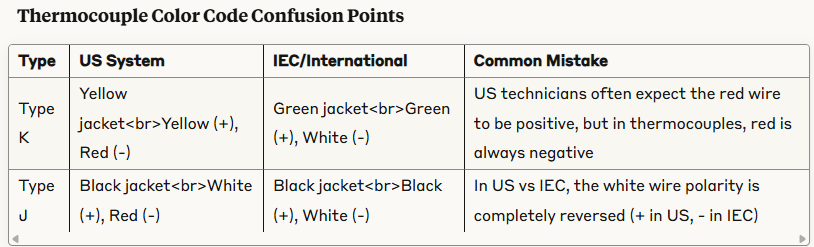
- Incorrect TC Type Selection: K vs J type misconfigurations create significant measurement distortion. This can be confusing when using color codes from different standards/nationalities.
- Reference Junction Compensation Errors: Disabled or incorrectly configured CJC introduces substantial offsets.
- Extension Wire or Connector Mismatches: Wrong extension wire creates parasitic junctions and inconsistent readings.
TC Case Study 1:
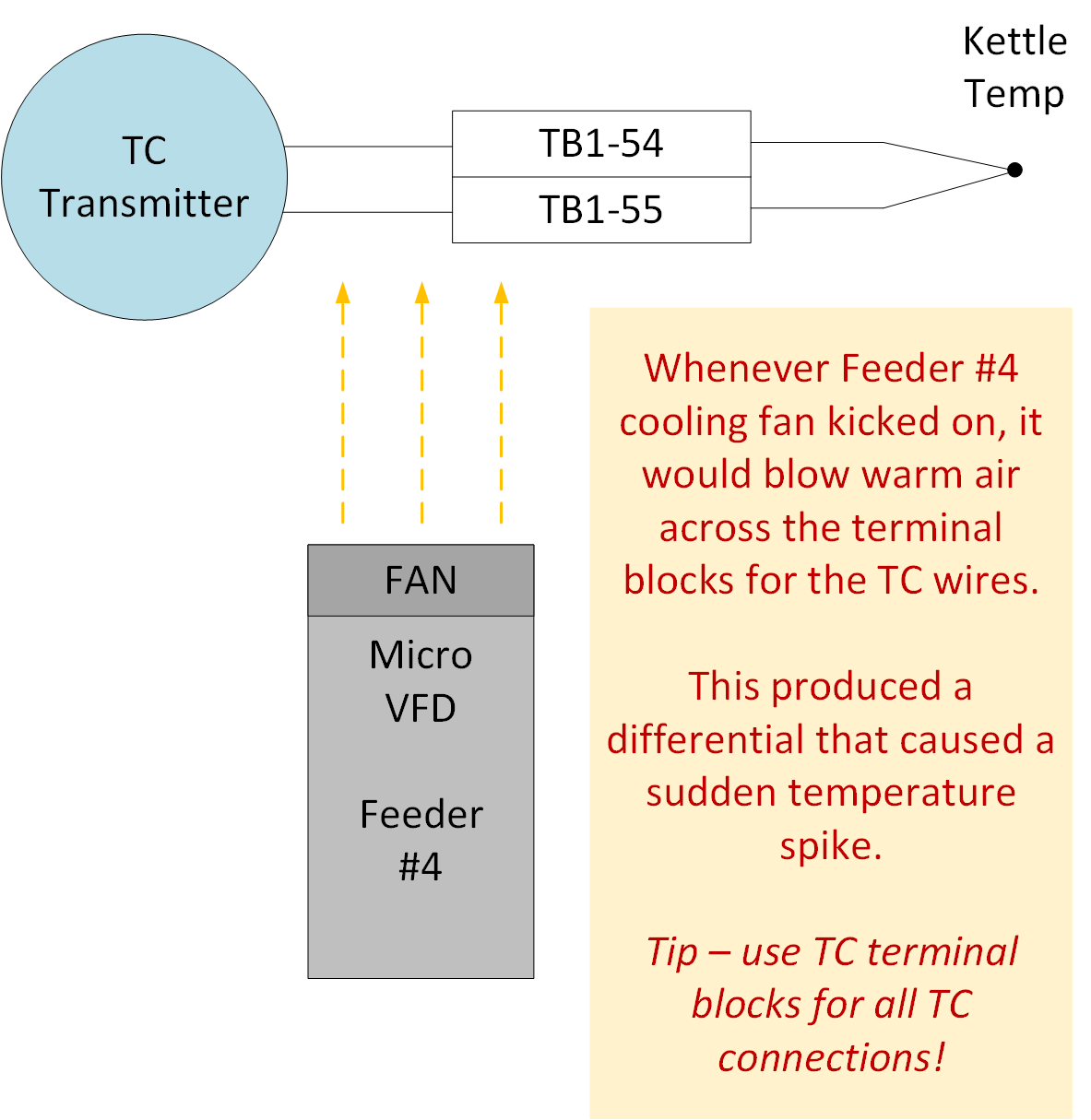
In this scenario, a small VFD that ran a 1/2HP feeder was located below some standard terminals where some thermocouple extension wires ran through. The integrator naively assumed (it was me) that there should never be a temperature difference across the terminals so saved a few dollars by not using TC extension blocks designed specifically for TC's.
But the VFD would occasionally kick on a fan to remove heat as it powered the feeder motor. When that happened, one side of the terminal blocks would be heated up by 5-10F or more - and would cause an imbalance in the thermocouple junction voltages across the terminal blocks which would mysteriously throw off the kettle temperature readings dramatically. Luckily it was a small system with only 50-60 total IO, so a quick review of the process trends showed that the spikes always happened when feeder 4 was running and tended to occur for few minutes the whole time it was on. Didn't take long to figure out the problem and resolve it - but it was a great lesson learned. Now days, this engineer always uses the specific TC terminal blocks for TC extension wiring...
Solutions:
Implement formal written color-coding and thermocouple configuration & verification procedures during installation and maintenance.
Source thermocouples that match color code standards.
1.3 Pressure, Level, and Flow Sensor Configuration Issues
Key Problems:
- Units Incorrectly Configured: Scaling or configuring transmitters or controllers with wrong units.
- Inaccurate Density/SG Settings: Outdated fluid property values in flow computers create proportional measurement errors.
- Incorrectly Applied Strapping Tables or Linearization Curves:
- Wrong K-Factors: Using generic (assumed) rather than device-specific calibration factors in turbine meters.
- Hidden Compensation Curves: Modern multi-variable transmitters applying proprietary compensation curves that conflict with DCS algorithms.
- Misapplied Viscosity Corrections: Incorrect or outdated viscosity values used in flow calculations for positive displacement meters.
Solutions:
- Maintain configuration management database for sensor-specific parameters with formal change control.
- Audit multi-variable transmitter configurations, against DCS scaling.
2. Improper Instrument Installations
2.1 Pressure Measurement Installation Issues
Key Problems:
- Impulse Line Traps or Pockets: Gas or liquid pockets in impulse lines causing inconsistent readings and pressure spikes. Note – this is a very common problem.
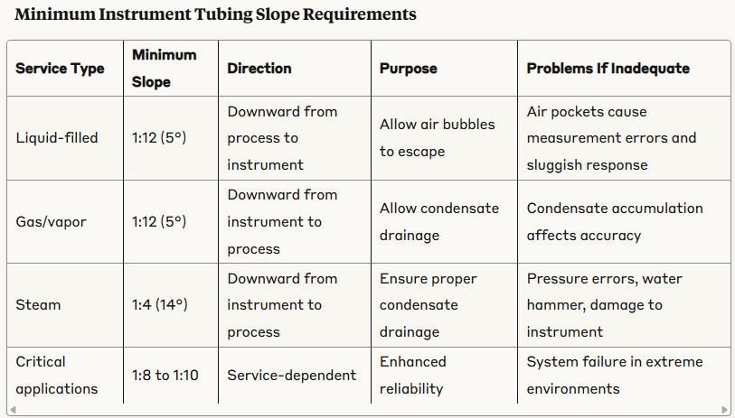
Case Study: Beautiful tubing – but completely horizontal runs (no slope) and multiple pockets per run on numerous systems (on a large deepwater production facility).
- Unequal Capillary Lines on DP Transmitters: The H and L port capillary lines for a DP transmitter should be approximately the same length and routed in similar temperature to ensure the temperature effects balance out.
- For example; if one line is routed in hot or sunny area and another is routed in cooler or shady area, they will read differently just do to thermal effects.
- A longer capillary line will also suffer more thermal impact than a shorter one – so each line should be approximately equal lengths.
- Vibration Interference: Direct mounting to vibrating equipment creating signal noise and premature failure.
- Thermal Impacts of Wet Legs: Filling (and/or blowing down) a wet-leg can result in liquid in the line that is at a different temperature from normal, resulting in different head pressure and a temporarily erroneous DP value.
- PSIG Reference Taps Incorrectly Routed: If the reference leg of a DP measurement (such as level) is not routed to the same pressure that is blanketing the measurement leg, it will result in deviations.
- Heat Tracing Problems: Inconsistent heat tracing application causing temperature-dependent errors in pressure readings.
- And many, many more – Installation design mistakes seem to be increasing as experience retires and training dwindles.
Solutions: The solutions for nearly all of the installation problems are the same: Establish clear, detailed engineering design and installation standards (with explanations and exceptions) and enforce them. Treat the design and installation standards as a living document as part of the engineering lifecycle and update as needed to ensure the standard can be followed.
2.2 Temperature Measurement Installation Issues
Key Problems:
- Inadequate Immersion: Insufficient thermowell depth causing stem conduction errors.
- Excessive Thermal Mass: Oversized thermowells introducing measurement lag in dynamic processes.
- Missing or Degraded Heat Transfer Compound: Poor thermal contact between sensor and thermowell. Note – Some systems use spring tension to ensure firm contact of probe to thermowell.
- Mechanical Binding: Improper installation of displacer/float mechanisms creating stiction.
- Installation-Related Beam Blockage: Radar or ultrasonic signals partially blocked by internal structures or build-up.
- Incorrect Mounting Angle: Angled installation of non-contact level devices creating trigonometric measurement errors.
Solutions: Establish clear, detailed design, installation, and commissioning checklists.
2.3 Level Measurement Installation Issues
Key Problems:
- Incorrect DP Level Calculations: This is a very common problem. If the engineering design is not explained or detailed, it may be questioned or cause confusion, or field personnel may make configuration adjustments based on assumptions in an attempt to correct other problems. Common confusion points are: SG of product and/or capillary lines not factored correctly; Using incorrect height distances; Confusing Inches of water column (IN-H2O) with inches of distance / height (transmitter URL and LRV will typically be in IN-H2O).
- Reference Leg Inconsistencies: Wet reference legs with evaporation or condensation issues causing drift, or variations due to temperature (density) changes of fill liquid (such as in steam-water interface measurement with condensing pots after blowdowns).
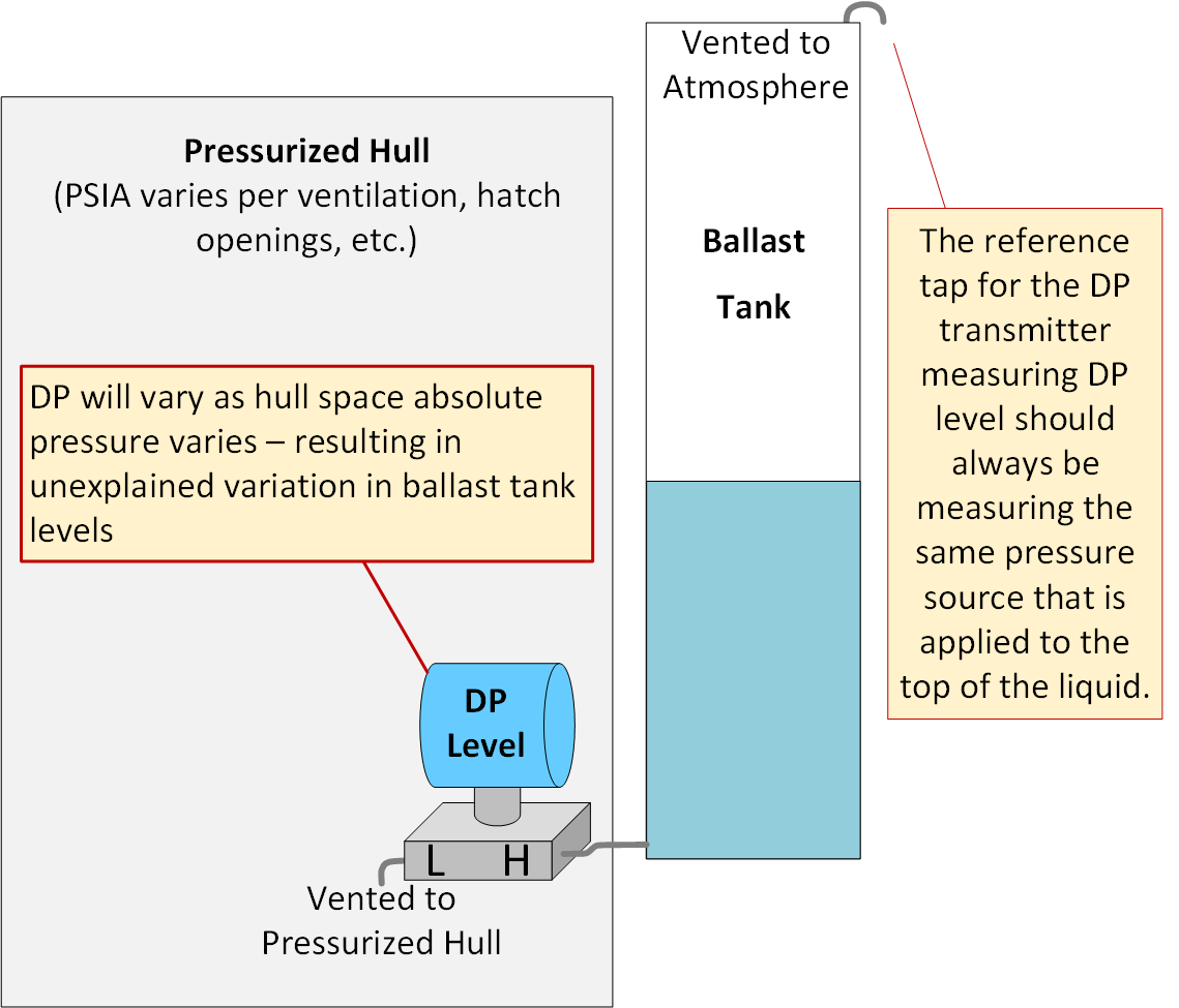
- DP Level - Reference Leg Mistakes: DP level transmitter static pressure reference leg not measuring liquid blanket gas pressure, resulting in incorrect compensation.
Case Study (Reference Leg Mistakes): In the example below, a DP level transmitter is mounted in the pressurized hull of a marine vessel for ease of access, but it is measuring the level of a ballast tank which is vented to atmosphere. The inconsistency between the psia of the pressurized hull and the psia of the atmosphere will cause variations in the indicated level.
Solutions: Establish clear, detailed design, installation, and commissioning checklists.
2.4. DP Flow Measurement Mistakes
2.4.1 DP Flow Below Turbulent Region: In some cases, the process flow of a system ends up being operated BELOW the established turbulent flow characteristic range.
If Reynolds numbers drop too low, the laminar characteristic along sidewalls of the piping results in a skewed, lower than actual indication of DP and therefore a lower flow.
The flow MUST remain in the turbulent region to ensure accurate flow rates. If the process requires flows below the turbulent range, system modifications may need to be made (smaller diameter pipe, etc.)
It is common for operations (and even some technicians and engineers) to assume that DP flow is accurate down to zero flows - but in reality, most DP flow measurements become increasingly inaccurate the lower in the range they go. This increase in errors at low end is due to 1) the amplification of errors on the low end due to the quadratic nature of the DP vs Flow curve, and 2) due to the transition to laminar flows as the velocity decreases. Laminar flow is bad news for DP flow measurements. See our our blog showing our Sample Instrumentation Progress Workbook on Flow for more information.
Solution: Establish clear, detailed design, installation, and commissioning checklists and enforce management of change policies to ensure no unsanctioned changes.
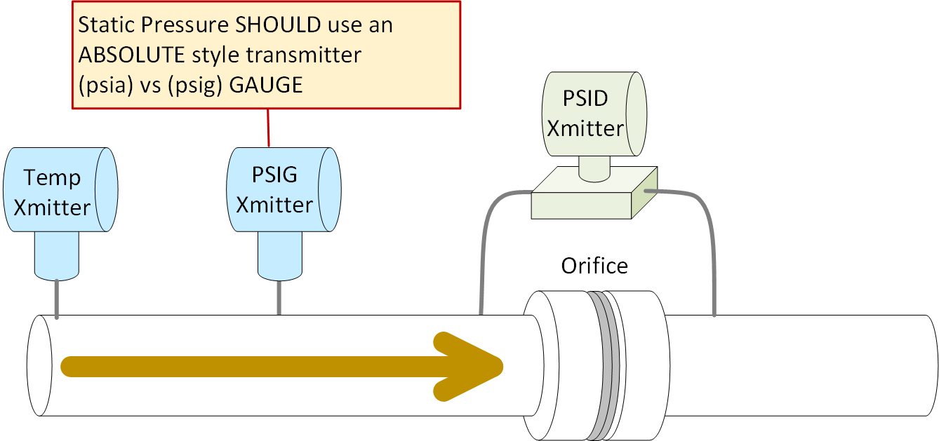
2.4.2 Static Pressure Not Measured in Absolute Scale: Gas flow calculations must compensate for gas density – but this compensation is based on absolute pressure.
Case Study: For whatever reason gauge style transmitters are often used in this situation and a constant of 14.7 is simply added to the raw PV in the controller to produce the required PSIA value that is used in the flow calculations in controller. This might work if atmospheric pressure was always fixed at exactly 14.70 psi - but it is not.
However, actual atmospheric (barometric) pressure is not always 14.7psia. Even at sea level, it varies by +/- 0.5psi – so the density compensation can produce considerable amount of varying error.
This is especially important at lower static pressure ranges because the 0.5psi variability becomes a more significant portion of total static pressure. This seems to be a common engineering oversight.
Solution: Establish clear, detailed design, installation, and commissioning checklists.
3. Improper Instrument Selections
3.1 Level Measurement Selection Mistakes
Key Problems:
- Technology vs. Process Mismatch: Ultrasonic sensors in variable density gas environments; DP level in variable SG applications.
- Environmental Compatibility Issues: Instruments selected without considering coating, corrosion, or fouling factors.
- Range vs. Resolution Tradeoffs: Over-ranged instruments with inadequate resolution in normal operating region.
- Surface Condition Sensitivity: Using radar on turbulent or foaming surfaces without appropriate signal processing.
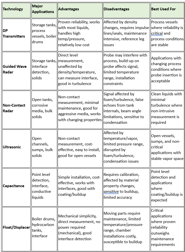
Level Measurement Technology Comparison
Solutions:
- Conduct thorough application analysis considering all process variations before technology selection. Note – chart above is general in nature. Specific brand and model details must be fully factored in as well as process and application details.
- Create clear, detailed specification / installation / commissioning checklists and adhere to them rigidly.
3.2 Flow Measurement Selection Mistakes
Key Problems:
- Operating Principle Limitations: Mag-meters in low conductivity applications; turbine meters with variable viscosity.
- Turndown Requirements Mismatch: Selected technology cannot handle the required flow range.
- Installation Constraint Ignorance: Insufficient straight run availability for technologies requiring it.
- Reynolds Number Effects: Flow instruments selected without considering how Reynolds number changes across operating range.
- Two-Phase Flow Issues: Single-phase measurement technologies used in applications with entrained gas or solids.
Summary of typical Flow Measurement Technology Comparisons:
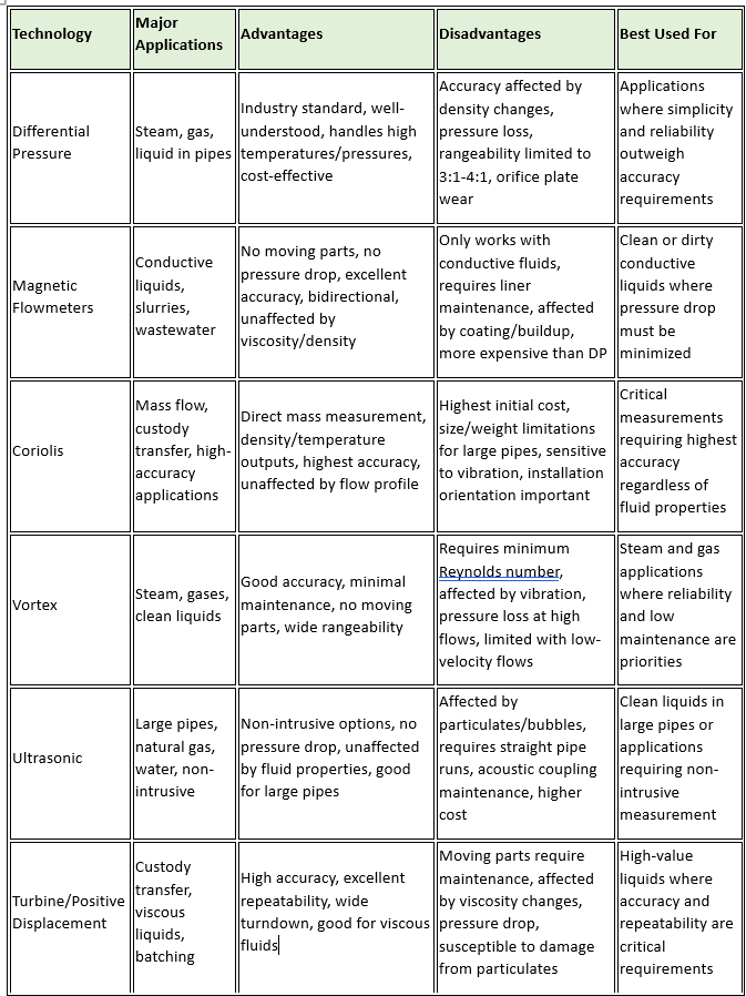
Solutions:
- Document complete fluid properties matrix and validate technology selection against full operating envelope.
- Consider multi-variable compensation for applications with varying fluid properties.
- Create checklist for any DP based measurements to ensure proper designs, compensations, etc.
- Note 1 – Temperature must also be in absolute format in the equation, but this can be done purely via algorithms by adding the offset for Kelvin to Celsius or Rankine to Fahrenheit since those relationships are constant. Perhaps the fact that temperature can easily be ‘converted’ is what leads to the confusion that we can simply add 14.7psi to a gauge style transmitter PV to obtain the absolute pressure..?
- Note 2 – If there is an accurate barometric pressure measurement available, that could be used in place of the generic 14.7psi value to accurately convert a psig reading into psia.
4. Unsanctioned, Improper, or Misguided Field Modifications
I call this the Get-R-Going-Again section. This includes ‘midnight maintenance’, ‘don’t ask – don’t tell’ tasks, and similar practices that are overly focused on a short term vision of plant performance. Poor leadership will encourage and reward these behaviors, greatly increasing the number of problems introduced and ironically increasing the amount of work needed, while reducing runtime, and degrading overall performance. Even sites and industry segments with detailed MoC procedure requirements often suffer these problems for numerous reasons.
4.1 Transmitter Parameter Adjustments
Example Problems:
- Errant Transmitter Adjustments: In order to satisfy demands from Ops or Management, field personnel with inadequate training / knowledge often make adjustments to various transmitter settings (URV/LRV, SQRT, Strapping Tables, Damping, Cutoff Values, Echo threshold, Blanking Distances, etc.) without proper understanding.
- "Temporary" Fixes Becoming Permanent: Modifications made during startup that address symptoms rather than causes often become normalized and accepted (without proper oversight or records of the changes).
Solutions:
- Enforce management of change policies for all configuration parameters with approval requirements and adhere to them rigidly. Maintain backup copies of original configurations (preferably digital copies of configs by tag name).
- There is no substitute for proper training of field technicians in this category (among others). If they don’t understand the issues and concepts at hand, they often simply ‘don’t know what they don’t know’. So, they will do whatever is needed to satisfy ops or management – period! Including guessing / hoping / making changes. If field personnel understand the basic concepts, they are more able to find the problems and are less likely to guess or make things worse, and they’ll at least realize what they don’t know and recognize when it is time to call for help.
4.2 Algorithm and Conversion Changes
Key Problems:
- Incorrect Flow Calculations: Wrong coefficients or dimensional data in flow algorithms. Assumptions such as copy/paste from one section of logic to another (instead of using tag specific data sheets for a particular primary flow element for example).
- Incorrect Level Calculations: Wrong values for DP level heights, SG’s, etc. as previously discussed; Or incorrect entries on radar, ultrasonic, or other types of level transmitters.
- Scaling Mismatches or Misalignments: Changing scaling on transmitter, analog inputs, control system logic, and/or HMI’s without matching the others.
- Linearization Table Errors: Improperly modified strapping tables or linearization curves.
- Competing Corrections: Multiple sequential adjustments by different personnel, with each unaware of previous changes. If there is no big picture strategy or approach to overall results (with applicable information being dispensed), this is likely to occur in many areas.
- Incorrect Compensation Factors: Temperature/pressure compensation applied incorrectly or with wrong coefficients. Another problem is applying a fixed (normal) value where the actual value may vary.
Solutions:
- Require peer review and validation against design documentation for all calculation parameters.
- Implement configuration version control with documented change history. Avoid ‘quick fix’ changes that have little or no engineering oversight or secondary review.
4.3 Signal Conditioning Modification Mistakes
Key Problems:
- Improper Trim Adjustments: Using zero/span trim to compensate for process issues rather than addressing root causes.
- Filter Setting Changes: Modifying filter settings to hide intermittent problems, masking diagnostic information.
- Hidden Configuration Parameters: Secondary parameters (low-flow cutoff values, noise rejection settings) modified without documentation.
- Inappropriate Noise Rejection: Excessive digital filtering masking legitimate process variations.
Solution: Develop clear guidelines for appropriate signal conditioning adjustments with emphasis on root cause analysis. Document all transmitter parameters including secondary configuration options.
5. Poor Maintenance Practices
This section should go hand-in-hand with Poor Root Cause Analysis (RCA) practices.
As a general rule, maintenance is one of the most overlooked aspects in plant reliability. Most sites should realistically step back and do a serious study on what maintenance they do (and why) and what maintenance they aren’t doing (and why not)…
Likewise, if a site is not doing proper root cause failure analysis they are unlikely to see the tremendous cost of some of their maintenance oversights and problems.
I have seen sites who poured millions of dollars into maintenance efforts still fail to recognize incredibly simple issues like corrosion buildup on control valve stems, air quality problems, poorly sealed panels and j-boxes, etc… All of which should have been identified if proper RCA’s were being completed upon each failure. But too often, the rush is to just get the plant running again and the RCA blank is simply filled in as a ‘failure of FCV 1004’ without explaining why or how… If industrial grade I&C equipment is failing often enough that it is considered routine and ‘acceptable’ as a failure on it’s own merit – The maintenance program may need a serious revamp. Unless you are purchasing low end equipment from known subpar locations or vendors, there are usually reasons these things fail. Most of the brand names in the I&C world deliver pretty reliable equipment these days – as long as it properly installed, configured, and maintained.
On a related note – Too often, sites fail to review the maintenance requirements of the boring, ‘less fancy’ or less technical equipment. If a site requires the O-rings to be lubricated or a small part to be replaced every year - you better schedule that in – or just plan on the downtime and problems that the skipped maintenance will eventually cause.
5.1 Mechanical Measurement Maintenance Issues
Key Problems:
- Neglected Impulse Lines: Sludge accumulation creating damping effects and response delays.
- Plugged Sensor Ports: Process buildup affecting measurement sensitivity and response time.
- Seal Pot Level Variations: Unmonitored changes in seal pot fluid levels affecting DP measurements.
- Air Supply Neglect: This is a huge overlooked source of improvement. This will be covered in more detail in part 4 on final control elements, but it can also be a big source of problems with measurement systems that utilize air, such as bubbler level measurement systems, purge / back pressure systems, etc..
Solution: Implement process-specific mechanical maintenance procedures based on fluid properties and operating conditions.
5.2 Electrical System Maintenance Issues
Key Problems:
- Aging I&C Power Supplies: Increased ripple voltages as old style power supplies age and/or become overloaded – Can inject noise onto the signal lines and cause other problems.
- Poor or Incorrect Grounding: Improper grounding can negate protection provided by transient suppressors, lightning arrestors, etc., resulting in equipment damage that is often unknown, but which can throw off readings and cause errors and premature failures.
- Improper Signal Shielding: Ensuring signal shielding is performed according to specifications will help prevent ground loops and other problems that can induce noise onto signals. Ground loops are especially challenging because they are often random and inconsistent in when/how much they impact the signals – so good installation practices are paramount.
- EMF Noise: Electrical noise can be induced into signal lines in a number of ways. Good electrical installation procedures (and/or simply following applicable electrical codes) can prevent most of the potential problems.
Solution: Adherence to Federal and local electrical standards such as NFPA, NEC, etc.
5.3 Instrumentation & Calibration Program Issues
Key Problems:
- Inadequate Settling Time: Failing to wait 7-10x time constants before taking calibration readings or making adjustments, leading to inaccurate calibration results
- Outdated Calibration Programs: Using procedures, forms, and methods designed for 1980s technology that fail to address modern smart instruments' capabilities and requirements. See our blog on outdated calibration program issues here: Automation Insights - Blog | Orion Technical Solutions
- Inadequate Calibration Intervals: Using arbitrary fixed intervals rather than evidence-based frequency determination based on instrument drift history and process criticality
- Test Equipment Connection Errors: Improper simulator hookups (such as using jumper wires on 3/4-wire RTD transmitter calibrations) that introduce measurement errors
- Environmental Test Conditions: Failing to account for ambient temperature effects on calibration equipment or physical media trapped in test lines
- Data Resolution Deficiencies: Recording rounded values (e.g., "one hundred percent" vs. "99.97 percent") that mask small but critical deviations
- Inadequate As-Found Documentation: Not properly documenting initial conditions before adjustments, preventing drift analysis and obscuring degradation patterns
- Calibration Scope Limitations: Only checking a subset of the full instrument range or focusing solely on zero/span while ignoring linearity across the range
Solutions:
- Establish Calibration Science Principles: Develop universal calibration fundamentals applicable across instrument types (settling time, resolution requirements, documentation)
- Implement Data-Driven Calibration Intervals: Replace fixed time-based calibration with statistical process control approaches using as-found/as-left data to optimize frequencies.
- Modernize Calibration Documentation: Redesign forms and procedures specifically for smart instruments, including parameter documentation fields for damping, filter settings, etc.
- Standardize Critical Procedures: Create detailed, instrument-specific procedures for complex devices rather than generic instructions
- Enhance Technical Training: Train technicians on instrument theory and first principles rather than just procedural steps
- Implement Digital Calibration Management: Use calibration management software to track drift patterns, optimize intervals, and maintain complete configuration histories
- Establish Performance Verification Standards: Define acceptance criteria that include response time and dynamic performance, not just static accuracy
- Conduct Regular Program Audits: Review calibration results to identify systemic issues and refine procedures based on actual field performance
5.4 Documentation Discipline
Key Problems:
- Undocumented Temporary Changes: Making "quick fixes" during troubleshooting without documentation.
- Use of unsanctioned references, procedures, etc.
- Handoff Communication Failures: Incomplete information transfer between shifts or technicians and/or during installation or commissioning or other stages of a project.
- Configuration Backup Neglect: Failure to maintain backup copies of transmitter configurations before changes.
- As-Found Condition Omissions: Not recording initial conditions before making adjustments.
Solutions:
- Enforce documentation for all configuration changes and implement formal handoff procedures.
- Require as-found readings before any adjustment is permitted.
- It is a good idea to train on documentation requirements as part of other technical training to help explain the how and why of documentation so personnel get on board and better support the documentation programs.
6. Worker Competency Issues
6.1 Poor Foundational Knowledge

Key Problems:
- Basic Principle Gaps: Lack of understanding about measurement fundamentals leading to improper troubleshooting.
- ‘Check the Box’ Training, Development, and Assessment Efforts: Training and developmental related programs must strive to solve problems in the field, vs satisfying spreadsheets or KPI’s. Downtime, swapped parts, MTBF trends, quality problems, safety incidents or near misses, and other performance factors should be leaned on more as metrics for proper training.
- Procedural Misunderstandings: Critical errors like improper manifold operation causing equipment damage.
- The "Tribal Knowledge" Gap: Critical techniques passed through apprenticeship rather than formal documentation.
- "It's Always Been Done This Way": Perpetuation of legacy practices without understanding the principles.
Solutions:
Develop detailed technical role expectations and competency standards – the more detail the better.
Provide general training on core ‘generic’ concepts.
Create site-specific training on details of high importance, high complexity, and/or where errors have been common. It is a good idea to save these trainings on a shared drive for later re-use as needed (I call this “on demand” training). These trainings should be more than policy statements – they should include the “how’s” and “why’s” along with the “be sure to…” and “watch out for…” type issues.
Identify the natural mentors and top-skilled personnel remaining in your organization, and implement them heavily in developmental programs and knowledge capture efforts while you still can. Beyond just passing on their knowledge, these are the individuals who can help junior personnel to realize what they need to learn (and that they do in fact need to learn it).
Document tribal knowledge through structured knowledge capture sessions and build into training and developmental plans.
Ironically, training is the #1 solution to most of these problems. A well-trained technician will recognize a problem and is likely to bring attention to it. Poorly trained personnel often just continue to blindly do whatever they are told or shown.
Conclusion
Input accuracy and precision problems form the foundation of data corruption in control systems. By addressing these issues systematically through proper design, installation, configuration, maintenance, and staff competency, organizations can significantly improve the quality of process data and reach full potential in current control systems as well as capitalizing on new transformative technologies that are rapidly coming of age.
Technically, Industry 4.0 assumes all data is verified. Getting high quality data is arguably the FIRST step that should be completed on any digital transformation or controls project. Yet – I still see very little discussion, action, or emphasis on these boring technical details of ensuring that data.
Remember: No amount of analytics or signal processing can compensate for fundamentally flawed input data or source measurement problems. Solving problems at the source is always the most effective approach. The GIGO acronym holds true (garbage in = garbage out).
In our next installment (Part 4), we'll explore how output device behaviors and limitations contribute to data corruption in control systems.
About the author
Mike Glass
Mike Glass is an ISA Certified Automation Professional (CAP) and a Master Certified Control System Technician (CCST III). Mike has 38 years of experience in the I&C industry performing a mix of startups, field service and troubleshooting, controls integration and programming, tuning & optimization services, and general I&C consulting, as well as providing technical training and a variety of skills-related solutions to customers across North America.
Mike can be reached directly via [email protected] or by phone at (208) 715-1590.