Level DP Problem (Wet Leg tied to LP port)
Question:
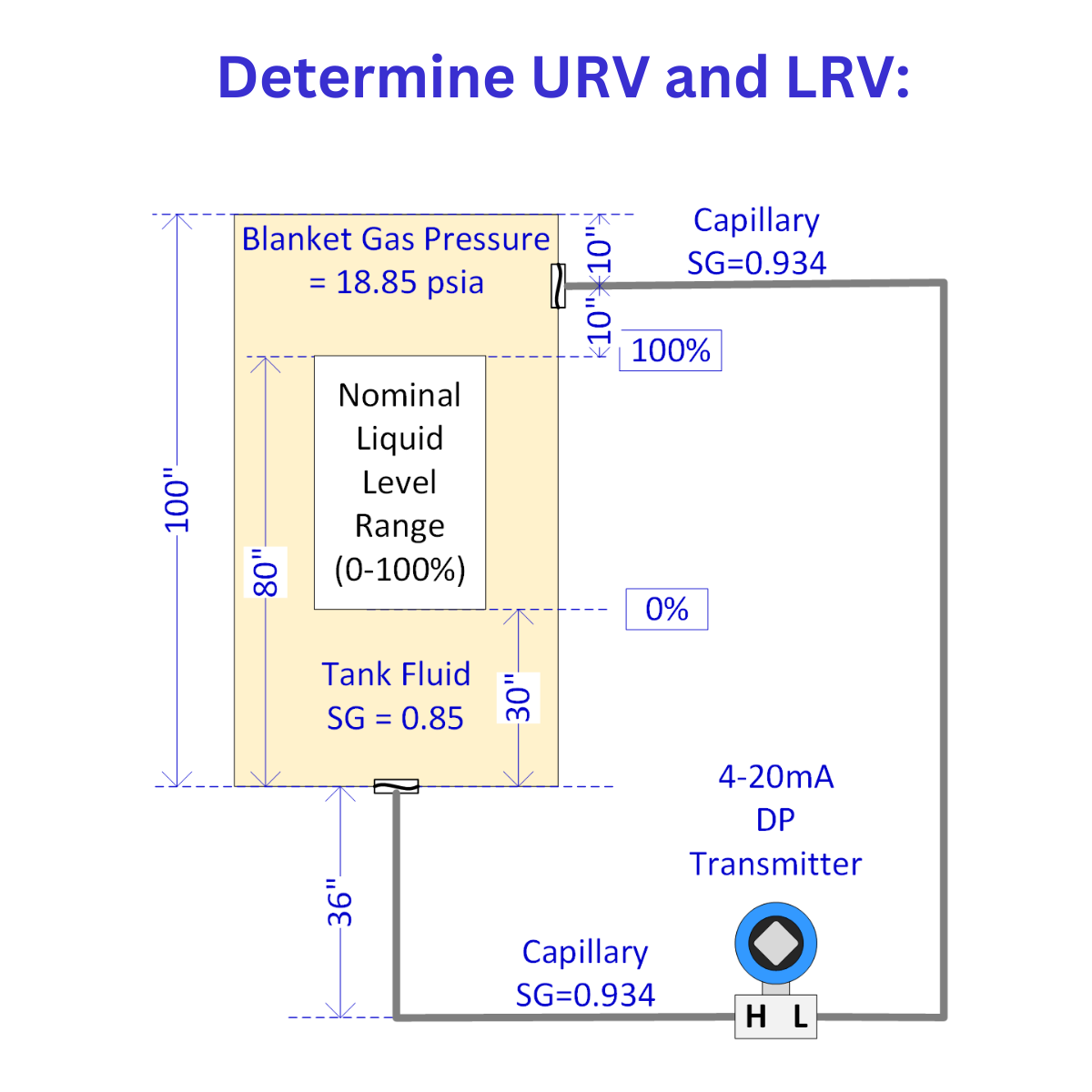
Determine required URV & LRV
Notes
1) The operating (0-100%) range is not from bottom to top of tank! It is from 30 inches above bottom of tank to 80 inches above the bottom of the tank. That is what you need to use for the LRV and URV.
2) One of the points of this problem is to factor in that as level increases the DP decreases, but the mA output of the transmitter needs to increase so that 100% = 20mA and 0% = 4mA. This is done in many different ways and is usually where errors are made in configurations.
3) Be sure to notice all given information:
- Gas Blanket Pressure (does it matter?)
- SG of capillary lines is 0.934 (Silicone oil DC200)
- SG of the fluid inside tank is 0.85
- Closed tank system with process fluid level between the 0% and 100% points shown
Learning Tip - There are many great excel tables and aids that can help on these problems but only AFTER you understand the concepts and terms. Here is a great example of a spreadsheet that can help on DP level calculations provided by AutomationTechTools.com at this link) - but be warned, if the concepts don't really make sense, and if you aren't careful in entering the data, the result will be incorrect. Learn the concept and then practice using the tool to coordinate the two so that you'll get the correct answers in the field. Once you are good at thinking through the concepts, it is super quick and easy to get Siri or other quick tools to do the simple math required.
The answer is provided below the diagram.
Notes:
1) System designed with reference leg connected to transmitter LP tap and Fluid (measurement) leg connected to the HP tap. When doing DP calculations, it is important to always subrtact the LP from the HP... DP = HP - LP. Since the LP is going to be the larger pressure, this is going to tend to result in negative DP's. But this is very common. According to the Instrument Engineers Handbook by Liptak about 70-80% of wet reference leg installations are configured this way. The exceptions (from Author's experience, tend to be in steam and power plant applications).
2) Additionally, as the level rises from 0% towards 100%, the differential pressure would decrease since the two levels essentially get closer. This could vary in a tall system with large differences between the SG of capillary tubes and fill fluid, but in most cases the DP will decrease as actual level rises.
3) The negative pressure concept is sometimes difficult to comprehend at first. The best way to visualize it is to do the calculations separately for 0%, 50%, and 100% and analyze the results as you go, and ideally to actually do a system configuration or calibration after doing those calculations to see it in action.
4) In a real application the bottom diaphragm would typically be mounted on the side of the tank to prevent the problems arising from sludge accumulation on the diaphragm. The drawing is shown with diaphragm on the bottom for simplicity and to help clarity the calculation aspects of the question. Real world designs must factor in details of the material being measured as well as the likely problems and maintenance issues - But that's another blog...
Solution:
Given parameters:
Tank height: 100"
Measuring range: 30" to 80" from bottom
HP tap: Bottom of tank
LP tap: 10" from top (90" from bottom)
Transmitter: 36" below tank bottom
Capillary fill fluid SG: 0.934
Crude oil SG: 0.85
Step 1 - Ignore the Gas Values
Gas pressure is negligible because gas pressure is applied equally in all directions and there is insufficient height for typical gas densities to produce any significant difference in gas head pressure.
Step 2 - Solve for 0% condition:
At 0% level (30" of crude):
HP side: Pressure from fill fluid + crude
= (36" × 0.934) + (30" × 0.85)
= 33.62" + 25.5"
= 59.12" water column
LP side: Pressure from reference leg fill fluid
= (36" + 90") × 0.934
= 117.68" water column
DP = HP - LP = 59.12" - 117.68" = -58.56" water column
Step 3 - Solve ror 100% condition:
At 100% level (80" of crude):
HP side: Pressure from fill fluid + crude
= (36" × 0.934) + (80" × 0.85)
= 33.62" + 68"
= 101.62" water column
LP side: Pressure from reference leg fill fluid (constant)
= (36" + 90") × 0.934
= 117.68" water column
DP = HP - LP = 101.62" - 117.68" = -16.06" water column
Step 4 - LRV and URV:
LRV (0% level) = -58.56" water column
URV (100% level) = -16.06" water column
Discussion:
With this configuration (HP to bottom, LP to top), as the level increases, the differential pressure decreases (becomes less negative - or closer to zero).
Many technicians (and engineers) have falsely just ignored the negative sign and mistakenly assumed the rising level caused a higher DP value (since the absolute number seems to increase). But it's very important to realize that as a negative number gets closer to zero, it's actual absolute value is decreasing. And that makes sense; because as the two levels get closer together they should have a smaller DP, and as there is a larger distance between them, there should be a larger DP.
The Other Design...
If the HP tap was tied to the reference leg (to top of tank) and the LP tap was tied to the measurement leg (bottom of tank), as the level increased you'd see a decreasing positive DP. It's doing the same thing, but because we reversed the HP and LP in the equation "DP = HP-LP) the number is now positive instead of negative.
It is important to fully analyze these problems and applications, so you understand what is going on in these systems and fully comprehend the negative sign in front of the DP values - so that you can troubleshoot them when things go wrong and so that you can be the person to figure out when the transmitter has been improperly configured, vs being the person who likely misconfigured it.
Learning Tip:
Get in the habit of doing a calculation like this to confirm the URV and LRV of DP level transmitters that you will work on and bring your scratch paper to the field as you do the config/calibration or whatever work you are doing to verify the concepts as you do them. This will result in the concepts being locked in so they are available in the future.
1.Note on Gas Blanket Pressure: The 18.85 psia gas blanket pressure shown is applied to both legs – so it cancels out. In reality if a tank was extremely tall and had a very large height of dense gas and considerable height between the fill fluid and the reference tap points, it could become a noticeable factor, but the author has never seen a system where this would matter.
About the author
Mike Glass
Mike Glass is an ISA Certified Automation Professional (CAP) and a Master Certified Control System Technician (CCST III). Mike has 38 years of experience in the I&C industry performing a mix of startups, field service and troubleshooting, controls integration and programming, tuning & optimization services, and general I&C consulting, as well as providing technical training and a variety of skills-related solutions to customers across North America.
Mike can be reached directly via [email protected] or by phone at (208) 715-1590.