NAMUR NE 43 Standards and Application Details (often missed)
What is NAMUR NE 43 and how is it used?
If you work with Safety Instrumented Systems, you have likely heard of NAMUR NE 43, as it is typically utilized to establish consistent signal standards. SIS makes heavy use of the fault mode of 4-20mA signals as part of the online diagnostics and fault reporting capability of instrumentation - so it is typically implemented in SIS applications.
NAMUR NE 43 standardizes 4-20mA signals including: Signal level standards, Failure mode and Self-monitoring functionality, Status indications, Response time requirements, Interoperability standards, and Testing procedures, among other things. We will provide a more detailed post on those details later. This article is on the signal levels.
NAMUR NE 43 signal levels
Contrary to common misconception, NAMUR NE 43 doesn't actually specify an exact value for transmitter alarm and saturation levels.
Instead, it provides a 'Range' for each instrument operational mode with appropriate optional buffer ranges to allow for variability between different manufacturers and utilizes a 'differentiation zone' between applicable alarm and saturation values to prevent any 'overlaps' between instruments and controllers, etc.
Ideally, there would be one set of standard 4-20mA values, and all brands and models of instruments would comply with them – but for various real-world reasons (such as legacy equipment and differing design details of instrumentation), a universal set of fixed values simply isn't possible. For example, many instruments and controller analog input cards are simply limited by electronic designs - So, the crafters of NAMUR NE 43 had to create a workable COMPROMISE that could factor in the real existing systems and devices but that could serve as a standard to prevent overlap of the saturation and fault indications - but it is up to the user to determine the exact values and to ensure all players on the system will work well together...
Misconception #1 - Purchasing instruments and control IO that is listed as NAMUR NE 43 compliant (or even configured with the Mfr's default NAMUR NE 43 settings) does NOT automatically ensure compatibility with other parts of your control system! The engineering team still has to review the min/max alarm and saturation values of all devices (transmitters AND controller IO cards) and find values that will work for all devices in the applicable system. Using NAMUR NE 43 compliant instruments simply ensures that it will be POSSIBLE to find values that will work with each compliant part of the system without undesired overlaps of saturation/fault mode signals.
Misconception #2 - The default values for NAMUR NE 43 compliant instruments varies considerably. If you desire a certain value for high/low saturation and fault values, it must be specified when ordering or must be configured during installation.
The specific 'default' values for high and low failure (alarm) and saturation can vary by manufacturer. In fact, values even vary between different instruments from the same manufacturer. See table below for example:
| Transmitter Model | Configuration | Low Saturation | High Saturation | Low Fault | High Fault | NAMUR Compliant? |
|---|---|---|---|---|---|---|
| Rosemount 3051 | Standard (Default) | 3.9 mA | 20.8 mA | ≤3.75 mA | ≥21.75 mA | NO - High sat in diff zone |
| Rosemount 3051 | NAMUR (C4/CN) | 3.8 mA | 20.5 mA | ≤3.6 mA | ≥22.5 mA | YES |
| Rosemount 3144P | Standard (Default) | 3.9 mA | 20.5 mA | ≤3.6 mA | ≥22.5 mA | YES |
Notice that the Rosemount 3051 in standard configuration uses 20.8 mA for high saturation, which falls in the NAMUR NE 43 forbidden differentiation zone (20.5-21.0 mA). This is why simply purchasing "NAMUR NE 43 capable" equipment is insufficient - you must verify the actual configured values and specify NAMUR-compliant settings when ordering for SIS applications.
So - NAMUR NE 43 sets a range of values for each 'signal level mode' that engineers choose from, to establish specific local standards for the applicable control system(s) so that all of their specific equipment will work well together.
Let's discuss the ranges that they select from. Refer to the visualization diagram shown below:
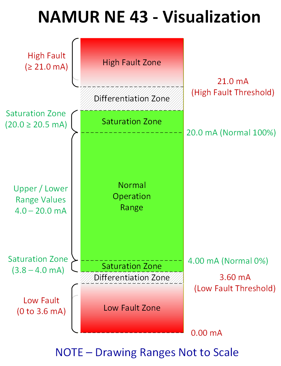
Notice the gray hashed regions. These are DIFFERENTIATION ZONES. These regions serve as a separation between the applicable Saturation and Fault Zone signal ranges.
The DIFFERENTIATION ZONES are critical features of NAMUR NE 43. These zones are intentionally undefined regions where compliant transmitters should never output signals.
The differentiation zone from 20.5 to 21.0 mA separates the high saturation zone from the high fault zone. NAMUR-compliant transmitters must saturate at or below 20.5 mA and must not output between 20.5 and 21.0 mA. Fault signals begin at 21.0 mA or above.
Similarly, the differentiation zone from 3.6 to 3.8 mA separates the low fault zone from the low saturation zone. NAMUR-compliant transmitters must fault at or below 3.6 mA and must not output between 3.6 and 3.8 mA. Saturation signals begin at 3.8 mA or above.
These gaps allow control systems to set detection thresholds (such as 3.7 mA or 20.75 mA) in the middle of the differentiation zones without risk of signal drift causing false alarms.
By establishing differentiation zones between fault and saturation zones, NAMUR NE 43 creates clear boundaries that prevent ambiguity between "process out of range" and "transmitter failed" conditions. This is critical for SIS applications where false fault indications could trigger unnecessary shutdowns, while missed fault detections could allow failed transmitters to go undetected.
However, not all "NAMUR NE 43 compliant" devices actually comply with the standard as written. For example, many Rosemount transmitters in their default "standard" configuration output 20.8 mA for high saturation - which falls directly in the forbidden differentiation zone (20.5-21.0 mA). To achieve true NAMUR compliance for SIS applications, you must specify NAMUR configuration options (such as Rosemount's C4/CN codes) when ordering, or custom-configure the devices during installation.
The end user still has to research their specific devices and systems to ensure that all those pieces of equipment will work together...
*Note - Some instruments aren't NAMUR NE 43 compliant, and do not fall within the values listed above! The engineering team must make no assumptions and must know the actual values for each device from transmitter to control system.
Approach for Standardization
If standardization of fault values across multiple vendors is important:
- Establish specific organizational standards (specs) for Saturation, Alarm, and Fault Values and ensure the Safety Lifecycle adheres to the standards at all stages (procurement, replacement, etc.).
- Specify exact values in procurement documents rather than just requesting "NAMUR NE 43 compliance"
- Verify actual values and functionality of saturation and fault alarm indications and behaviors during commissioning
- Document the actual values in your instrument database for future reference
- Test operation for each applicable signal mode prior to commissioning and per other testing requirements.
Implementation Considerations
When implementing standardized fault detection:
- Consider whether upscale or downscale failure mode is more appropriate (and safe) for each application. In many situations (especially in instruments that have high and low protective functions on the same instrument, there will be exceptions - so you cannot simply assume all instruments should fail high or fail low.
- Verify that the control systems are configured with appropriate fault detection settings and that they are tested initially and at an appropriate interval.
- Train maintenance staff on the standards and design intentions, including expected low detection, saturation, and fault values and any exceptions. This will aid their troubleshooting efforts as well as helping them catch mistakes and better follow testing procedures.
Other considerations in instrument signal design:
It is important to factor in the specs of the applicable controller IO when planning an overall control system design.
- For example: Many the input ranges of many control system analog cards are limited (especially on the high side) are not capable of reaching the high fault values...
- For example: ControlLogix 1756-IF8 card has a full current range of only 0-21mA. But 21mA is well below the actual default current values that most vendors use as the default NAMUR NE 43 current limitation.
- Technically speaking, these analog inputs max out right at the minimum high fault current ranges of the NAMUR standard and below the standard configuration for most instruments when selecting the NAMUR config option (unless values are specified lower). This presents a challenge - because there is inadequate overlap for full reliability detection of a high fault signal.
- The ControlLogix series is not ISA 84 / IEC 61508 compliant - You would need to utilize the GuardLogix series to achieve full SIS ratings. Other controller models have similar limitations. Most DCS systems that are SIL-2 rated are also NAMUR NE 43 compliant.
- It is helpful to have some form of database or spreadsheet of all devices used with applicable specs and limitations is an important step when plotting out an organization standard set of values to use for specific instrument saturation and alarm values. And the reality is that in some cases, you may have to make the dreaded exceptions to desired standards – but if it is noted in the standards with reasoning and personnel are trained accordingly, it can still work.
- Prior to inking a site standard or specification, it is wise to perform detailed mockup testing on the full range of equipment that will actually be utilized, including with all typical signal loop devices and arrangements (include any IS devices, etc.), and testing the full range of instrument outputs from disconnected & 0mA up through the max transmitter output. This is the best way to catch many of the problems that are often missed in SIS engineering design, and which can become a nightmare if not realized until after implementation.
Note - Though much of the above info is based (and mostly utilized) for in ISA 84 / IEC 61511 (SIS) applications, the same principles could (and really should) be implemented in all instrumentation & controls areas, from Basic Process Control, down to single loop controls or simple brick PLC systems. Anyone who becomes highly familiar with the brilliance of the SIS standards will see that they have really thought that through and figured out how to not only maximize reliability, but to track it and study it. Ideally, a plant could have a unified standardized approach that could apply to nearly all I&C equipment from basic support systems through full-blown Safety Instrumented Systems.
About the author
Mike Glass
Mike Glass is an ISA Certified Automation Professional (CAP) and a Master Certified Control System Technician (CCST III). Mike has 38 years of experience in the I&C industry performing a mix of startups, field service and troubleshooting, controls integration and programming, tuning & optimization services, and general I&C consulting, as well as providing technical training and a variety of skills-related solutions to customers across North America.
Mike can be reached directly via [email protected] or by phone at (208) 715-1590.