Instrumentation Question (Saturation & Alarm Concepts)
Question:
What would the mA output be?
A technician inadvertently enters 111 F instead of 100 F while testing a 4-20mA transmitter that is configured for 0-100F input.
Notes
1) Assume wiring and hookups are correct. Drawing is simplified for sake of clarity and generality.
2) If you don't know a specific detail that would typically be in the manuals, just estimate and list where you would find the information (be specific)
This seemingly simple topic is a very common weak area for many instrument technicians, and yet it needs to be clearly understood.
The answer is provided below the diagram.
Solution: 20.5 mA
Here's Why:
If we do a quick scaling calculation to determine what the 'linear' value would theoretically be (if transmitter curve was linear forever):
111/100 = 110% (= decimal fraction of 1.11)
1.11 x 16mA = 17.76mA + 4mA = 21.76mA
BUT... the transfer curve is NOT linear forever. It plateaus slightly above the 100% point. This is referred to as transmitter HIGH SATURATION as shown on the green line in illustration below.
![]()
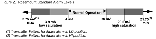
This occurs on the top and bottom ends of the 4-20mA curve. The saturation values vary by transmitter brand and model - but are typically in the 3.9mA range on the low end, and 20.5-20.8mA range on the high end (You should be able to find these values in the manual). See illustration below for an example of how it is shown in typical equipment reference manuals:
Troubleshooting Saturation on a transmitter:
If the HMI process value (PV) shows a consistent steady reading of 103% or -6%. This can easily be viewed by a trend. if the value was fluctuating and then hit a saturation point and flat-lined, it means there is something causing the transmitter to 'sense' a value that is well outside the normal expected range.
Why this matters:
This behavior of the saturation characteristics (and of the Alarm/Fail states) of transmitters is important because it is very valuable while troubleshooting. For example:
If a transmitter calibration has drifted it could possibly go slightly outside the 4.0 to 20.0 mA range...
but if it is steady at 3.9 or 20.5mA, it is likely saturated. This could be caused by many things such as errant configuration or calibration; incorrect sensor; etc.
If the transmitter output is at the high or low FAULT current levels, this could indicate problems such as: Disconnected sensor; transmitter configuration error; a transmitter diagnostic fault; etc.
Troubleshooting Related Issues:
Most higher end control systems will implement graphic clues as to the value of the 4-20mA when it is outside the normal range. This can vary, but it is wise for anyone who will troubleshoot the applicable systems to become familiar with the HMI codes and standards and the following common situations at a minimum.
For example, one possible layout might be as follows:
Transmitter Alarm / Fault - Many control systems will set a flag or bit if the transmitter output current reaches the high or low alarm output current (can be done in many ways).
The HMI is programmed to display something to alert operator to the condition and may even produce operator alarms, alerts, or warnings.
If you see that a transmitter has gone to a fault mode, it is NOT a calibration problem or something that is causing the transmitter to be inaccurate - it is something bigger, like a disconnected sensor or a true instrument electronics failure. Reverting to the High or Low Fault state is the transmitters way of screaming to you that it is not performing it's job, or it sees something that needs urgent attention.
These high and low alarm current values are well outside of the saturation range (by at least 0.5mA typically so they can be clearly distinguished from saturation points) - but know that the exact value for the alarm current is customizable within each transmitter (so each site needs a clear and consistent standard on what values are used for the high/low fault current).
Minus 25% A steady reading of -25% means that a 4-20mA has gone to 0mA. This usually means the signal wires have been disconnected or an open has occurred somewhere in the circuit.
NaN (Not a Number) - This often means the data is not available - not that it is simply outside a range (but in some systems it could also mean out of range, or other things - so know your system details).
Safety Instrumented Systems:
SIS programs (IEC 61508/61511 and ISA 84) make excellent use of the high/low fault alarm currents to help convey information about instrument status to the system among other things. Any technician working on SIS transmitters MUST understand the concepts of transmitter saturation and alarms to ensure proper maintenance and troubleshooting.
Learning Tip:
Find the applicable standards, reference pages, and information related to the above for each of your key systems and have it handy. Then refer to it when you see one of the conditions occur to lock in the concepts.
About the author
Mike Glass
Mike Glass is an ISA Certified Automation Professional (CAP) and a Master Certified Control System Technician (CCST III). Mike has 38 years of experience in the I&C industry performing a mix of startups, field service and troubleshooting, controls integration and programming, tuning & optimization services, and general I&C consulting, as well as providing technical training and a variety of skills-related solutions to customers across North America.
Mike can be reached directly via [email protected] or by phone at (208) 715-1590.