How many test points required in calibration check?
Question:
How many test points are required for an instrument transmitter calibration check?
Notes
1) Assume typical instruments such as process controls and process safety instruments that are not under special regulatory requirements.
The answer is provided below the diagram.
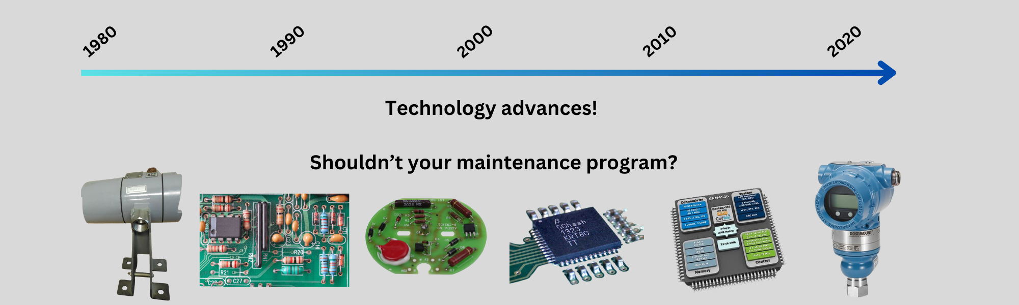
The Evolution of Instrumentation Testing
How many test points should be included in an instrumentation transmitter calibration check?
It's a question I've discussed with numerous colleagues recently, and the answers vary widely:
- 2-point end-to-end check (0%, 100%)
- 2-point edge-to-edge check (25%, 75%) or (10%, 90%)
- 5-point check (0%, 25%, 50%, 75%, 100%)
- 9-point check (0%, 25%, 50%, 75%, 100% upscale, followed by 75%, 50%, 25%, 0% downscale)
- And others...
But what should determine our approach? Ideally, our procedures and number of check points would be based on:
- The amount of specified (or observed) hysteresis in the instrument
- The specified (or observed) non-linearity in the instrument
- The specified (or observed) repeatability or precision of the instrument
- The allowable tolerance of the instrument
Unfortunately, the most common answer I hear for basis of testing methodology is: "That's how we've always done it."
The Legacy of I&C Traditions
Many of our calibration procedures and I&C maintenance strategies are based on what I call "I&C traditions" - practices developed for instrumentation technology from decades ago.
Those earlier instruments had moving parts like bellows, bourdon tubes, gears, LVDTs, capacitive DP diaphragm plates, and analog electronic circuits. These components created significant challenges:
- Large amounts of hysteresis and deadband
- Significant non-linearities
- Low repeatability
- High drift rates
To address these issues, many facilities adopted frequent calibration procedures with numerous check points, often including both up-scale and down-scale tests.
Today's Reality: Modern Instrumentation
The state of instrumentation has dramatically changed. Thanks to:
- Improved designs of sensors
- Introduction of microprocessors for calculations
- Decades of trial by fire for various sensors and technologies
- Advancements in electronic components
The errors in today's instrumentation are literally a small fraction of what they once were. As I noted in my blog on Calibration Frequency Mistakes, typical drift rates alone are often 20 to 40 times lower than their older counterparts - the very devices for which our maintenance programs were originally established. Linearity and hysteresis errors have similarly been dramatically reduced.
The problems that arise nowadays are more likely to be caused by the following, than by calibration errors of the transmitter:
- Installation mistakes (bad seals, bad crimps, damaged cables or wiring, etc.)
- Design mistakes (excess loop impedance, overloaded power supplies, inappropriate sensor technology, etc.)
- Damage or issues within the overall instrument loop (moisture ingress, corrosion, loose or damaged terminals or wiring, short circuits or partial shorts, etc.)
- Improper configurations or calibrations
The Case for Fewer Test Points
Many manufacturers now recommend only 2 or 3 check points in their calibration procedures (even for SIS proof test procedures). Why? Because they recognize that additional checks simply aren't essential.
Could a site still choose to perform 5 or 9-point checks "just because" it makes them feel better? Certainly! And in some cases, it makes sense to continue testing more points, especially if it doesn't require significantly more time and if there is some sound reasoning for doing so.
But consider this: For instruments where each test point requires several minutes to perform (such as actual level or flow manipulations, slow-responding systems, or transmitters with significant damping), the difference between a 3-point and a 9-point check can add 15-30 minutes or more to each calibration.
Real Impact Example: If a plant reduces test points from 9 to 3 on just 1,000 transmitters, it could save approximately 250-500 man-hours each cycle. That's valuable technician time that could be redirected to more productive work.
When More Test Points Are Still Justified
There are exceptions to the above, where more extensive testing remains appropriate:
- Instruments with mechanical sensors that involve motion, friction, or torque (likely to result in deadband/hysteresis):
- Capsule float level transmitters that might stick slightly inside a bridle
- Torque-based, rotary or linear motion based sensors
- Any sensor with notable physical movement or compression
- Instruments likely to exhibit nonlinearities:
- DP flow transmitters (more on this in a future blog)
- Chemical or analytical measurements
- Devices with mechanically oriented sensor systems
- Thermocouple and RTD sensors (depending on quality and configuration used)
- And many others – usually predictable by approach, but also in specifications
A Practical Approach to Modernizing Your I&C Maintenance
If you're considering updating your I&C maintenance program approach, here's a practical pathway:
- Compile your instrument inventory in spreadsheet or database format and ensure it is accurate
- Document actual required tolerances for each device or group of similar devices - not just "plant or site" generic tolerances, but the real limits before problems arise
- Identify candidates for potential maintenance improvements (by device or like group)
- Study specifications and calibration history to determine what changes might be warranted:
- Calibration frequency adjustments?
- Tolerance modifications?
- Reduced test points?
- Procedural changes?
- Test proposed changes with trial runs before full implementation
- Implement a strategic rollout plan once benefits are confirmed
Important Note: This topic is one of several related to overall I&C maintenance strategy issues. Along those lines, if you do reduce the testing frequency on some of your transmitters, you’ll be putting eye-balls on them less frequently – so it may be wise to implement walk-by visual inspections as discussed in my blog on Smarter Approaches to Instrumentation Maintenance. A single technician with a radio can efficiently complete these very beneficial inspections very quickly via a well-planned route and a checklist, and can provide dramatically more statistical reliability and performance benefit to a plant than spending time doing more exhaustive or more frequent calibrations on equipment that typically doesn’t require it now days.
Continuous Improvement Through Data
Track your calibration reports and monitor details such as:
- Types and values of errors found at each calibration interval
- Number of failures (and problems) reported throughout the year
- Troubleshooting scenarios for different instrument groups
- It is also helpful and wise to gather feedback from the personnel doing the work
Use this data to further refine your approach. You may discover opportunities to extend testing intervals or reduce test points across entire categories of instruments and/or you will find some situations where you need more frequent or more extensive testing…
The key is making decisions based on actual specs and performance data rather than tradition alone. The technology has evolved - shouldn't our maintenance practices evolve too?
About the author
Mike Glass
Mike Glass is an ISA Certified Automation Professional (CAP) and a Master Certified Control System Technician (CCST III). Mike has 38 years of experience in the I&C industry performing a mix of startups, field service and troubleshooting, controls integration and programming, tuning & optimization services, and general I&C consulting, as well as providing technical training and a variety of skills-related solutions to customers across North America.
Mike can be reached directly via [email protected] or by phone at (208) 715-1590.