Brain Teaser: Instrumentation Maintenance Strategy
Question:
Which of the following preventative maintenance tasks do you think would result in a higher overall reliability to a typical plant? For sake of this question assume reliability means: 1) Minimizing inadvertent trips and unplanned downtime. 2) Ensuring that the applicable instrument protective systems dependably perform their intended safety functions. What are the pros and cons of each option? What would the labor hour comparison be for each option?
Option A – Perform annual calibrations of every process transmitter on a facility. The calibration procedure shall include the following:
· Adjusting transmitter PV to exactly match the simulated sensor input value
· Adjusting the transmitter 4-20mA output to exact values
· Verifying the transmitter output aligns with controller / HMI value
Option B – Perform a walkdown check of each process transmitter every month. The walkdown procedure shall include the following:
· A physical inspection of transmitter, applicable cabling, and tubing
· Cross comparison of transmitter PV (via LCD) to the controller/HMI value
· Cross comparison of the transmitter PV to a alternative measurement of the same variable via mechanical gauge or associated safety/control transmitter
Note - The answer to these questions would largely depend on application specifics - but the discussion should hopefully highlight some ideas that most managers who are charged with running I&C programs, or ensuring process control or process safety need to be contemplating and factoring into maintenance strategies and approaches.
>>>>>>>>>>>>>>>>>>>>>>>>>>>>>>>>>>>>>>>>>>>>>>>>>>>>
Answer/Explanation:
While this question is somewhat vague and open to interpretation, it can hopefully still initiate the thought process that I’m trying to bring up, which is that we need to factor in the changes and advancements that have occurred in the I&C world into our maintenance procedures and plans.
Whenever I teach, assess, or work with I&C technicians or engineers, I often ask them what their job is, or what the purpose of certain procedures are. Very often, they say it is to ensure the instruments are as accurate as possible…. But in most cases, the real job is to ensure the instruments are ‘within tolerance’ and more importantly, that they perform their intended function reliably. But why do so many assume it is about ‘accuracy’?
Many of the I&C maintenance practices being utilized across industry were developed decades ago, back when typical transmitters drifted way faster than our modern Smart transmitters do (by a factor of 10 to 40 times, actually). See our blog on this topic.
The typical transmitters being used back when most of our I&C program maintenance plans and strategies were developed didn’t have high precision, temperature compensated IC chips, onboard microprocessors, or digital displays (or the associated ability to display internal PV, diagnostic alerts, percentage output, expected mA values, or other information).
Since so few people fully understand the details of modern instrumentation or Smart transmitters very well – a huge number of organizations simply carry forward the same practices that applied to equipment from back when the 70’s TV show ‘Gilligan’s Island’ was still airing new episodes.
Back then, we truly needed to check (and often needed to adjust) the instrument calibration every year - because the instruments drifted by 0.25 to 1.0% per year! That extremely high drift rate was statistically the most common problem point in the overall system - So, we focused most of our I&C energy and programs into keeping those instruments accurate. Thus, the mindset that an I&C tech/engineers job was to ‘ensure optimal instrument accuracy’ became lodged in our collective I&C consciousness.
But now, calibration drift rates are so much slower that they are no longer the most likely problem area of the overall I&C loop, so it becomes more important to test and verify the other (more likely) failure points.
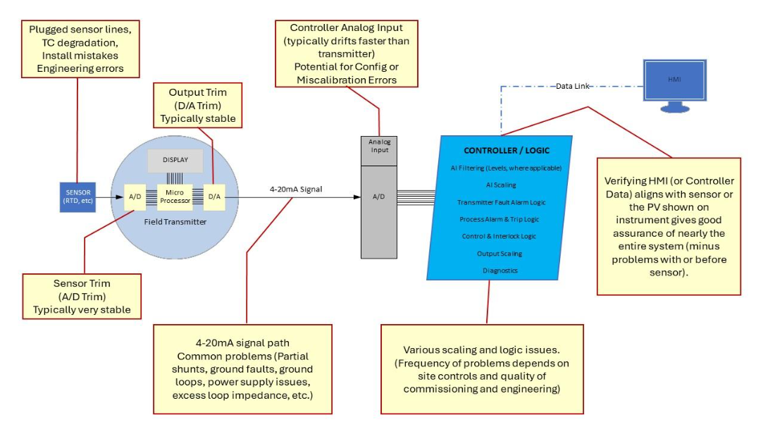
Look at the illustration of the entire loop for reference. Here are some examples of problems that create havoc in the I&C world (skip for non-techies):
- Moisture in a J-box causing a partial shunt of current flow and resulting signal mismatch between the transmitter signal and the applicable input card. See our blog on this topic for more.
- Drift of a PLC analog input card (which typically drift way faster than modern transmitters now).
- Physical problems such as sensor line traps or pockets or plugging.
- Changes in physical constants (SG, etc.)
Modern “Smart” instrumentation has very powerful display and diagnostic capabilities that simply were NOT available back in the days when most I&C maintenance programs were developed. The transmitter diagnostic capabilities of modern, Smart transmitters are incredibly powerful, and they should be implemented to a much greater degree than they are – but that’s another blog.
Sadly, many of those diagnostic error messages (even when they are configured and setup) go unnoticed for months or longer (which is a lead-in to my answer / explanation below):
So - instead of doing annual full-blown calibrations of ALL transmitters even though we have published verifiable evidence that most of these instruments drift less than 0.025% per year or less, many organizations could benefit by doing more frequent (but quicker, easier, and less invasive) walkdown checks of key transmitters and simultaneously reducing the frequency of some of the full-blown calibration procedures to the calculated periodicity per established vendor references (or regulatory requirements).
This is an offshoot of the concept of partial testing in the SIS world [per IEC 61511]. By checking the most likely (and easy to test) failure points in the loop more frequently, we can significantly reduce the amount of time that we operate with any undetected failures, and thereby reduce the average probability of failure on demand (i.e. we increase reliability and decrease the chances of a problem causing trips, downtime, or reduced protection). Of course, we still need to perform the FULL tests at some periodicity, but perhaps not as frequently as some are being performed...
The ‘walkdown check’ in my example would make use of the power of modern transmitters to check for the majority of the statistically likely problem areas (that are easy to check in a non-invasive way). This could include:
- An inspection
- Viewing transmitter display screen (where applicable) for any diagnostic alerts or warnings
- Cross-comparing the PV read on transmitter display screen to the HMI value to ensure it is within desired tolerance. This simple check can be done by a tech looking at transmitter PV and calling operator on radio for HMI value, and will easily find any notable errors between the transmitter and the HMI / Controller which is one of the most common problem areas in most facilities.
- Verifying the PV, as read on display screen aligns adequately to alternative measurements of the same parameter (such as the corresponding safety or control transmitter or mechanical indicators). This helps catch any sensor system errors or failures.
While the walkdown check does not provide quite the same level of accuracy as a detailed calibration procedure; and while an occasional full calibration procedure would still be needed at some interval – the simple walkdown check still verifies that each point in the system is functioning to a moderate degree of accuracy, and it would help find & identify the vast majority of the most likely potential failures, and would discover any significant drift problems way earlier. In short, we could KNOW there is an issue and fix it BEFORE it causes problems.
The benefits of the walkdown check over a full-blown instrument calibration are as follows:
- Non-invasive procedure (less likelihood of causing plant trips or upsets, or introducing configuration or calibration errors)
- No need for bypasses/overrides
- Minimal administrative overhead
- Easy to record/log results (pass / fail with comments for any findings)
- Earlier identification of any safety or control problems (less downtime, better reliability)
- This procedure, STILL finds any significant calibration drift problems in transmitter and throughout entire system – though not quite to same accuracy or detail level as a full calibration procedure.
- A single instrument tech could perform dozens of walkdown checks in the time it typically takes to complete a single full-blown calibration procedure. This means we can find more of the issues that lead to failures and problem, quicker and easier.
Sidenote – if you are thinking, “Why shouldn’t we just get an online HART or other Fieldbus system with existing smart transmitters, and setup the system to do the cross comparisons automatically and alert us as soon as anything drifts out of a tight tolerance window or as soon as any diagnostic alerts occur?” - the answer is probably YES - you should be doing that! Disappointingly, very few organizations take full advantage of the I&C equipment or the automation systems they utilize – and most could benefit tremendously just by thinking freshly and factoring in the capabilities of equipment they already have. I could rant volumes about the lost reliability opportunities in I&C and automation world, but hopefully that gets the thinking going.
The calibration “accuracy” misconception:
Realistically, most I&C field calibration equipment is not nearly as accurate as the modern transmitters that we are testing with them. This may seem counterintuitive to most and it causes a lot of confusion and misconceptions. Go look at the specs – and let me know if you find exceptions with any typical field or calibration equipment.
So, when a technician (who thinks they are being a ‘perfectionist’) makes those small calibration adjustments to a modern smart transmitter, they are often just ‘mis-calibrating’ it, so it now has the same error as the field calibration equipment used to calibrate it.
Back in Gilligan’s day, field calibration equipment was often more accurate & stable than the field transmitters they were used to test – but that all changed decades ago as the technology advanced. The benefit of field calibrators now days is that they are durable and easy to send in for secondary calibration and overall traceability. But they are rarely more accurate than the devices they are used to verify or calibrate. The real purpose of most field calibration equipment is simply to provide traceable evidence that any errors are within the specified tolerance envelopes.
Summary:
All of us in the I&C, Controls, and Process Safety world should better understand modern instrumentation technologies and changes, and should take a closer look at our I&C maintenance plans and programs to ensure we are factoring in the advances, capabilities, specifications, and statistical data of our equipment and systems.
The illustration below shows some of the likely failure points in a typical instrumentation input loop. You’ll note that the two failure points involved with the field transmitter (that get the most attention in calibration programs) are only a small portion of the actual issues that cause downtime, reduced safety margins, etc.

About the author
Mike Glass
Mike Glass is an ISA Certified Automation Professional (CAP) and a Master Certified Control System Technician (CCST III). Mike has 38 years of experience in the I&C industry performing a mix of startups, field service and troubleshooting, controls integration and programming, tuning & optimization services, and general I&C consulting, as well as providing technical training and a variety of skills-related solutions to customers across North America.
Mike can be reached directly via [email protected] or by phone at (208) 715-1590.